Category Archives: Uncategorized
Ports used to connect to ZeeVee Maestro application
You are required to login to view this page.
Stewart Audio FLX family amplifiers
To update the Steward Audio FLX family units, please follow the procedure below.
Audinate Version V3.10.4.1
Update for all units.
Corrected Issues:
- The firmware corrects a loss of audio between Dante based devices after an extended static operating period (typically > 1 month)
Update procedure (unzip files first after download)(login needed):
- Install the DanteFirmwareUpdateManager-3.10.0.9
- Update the ult-01-004-3.10.4.1 firmware version.
Please note that the above steps need to be done in sequence, otherwise the device will fail.
Stewart Audio AV-25NET and AV-25NET+amplifiers
To update the Steward Audio AV-25NET and NET+ units, please follow the procedure below.
Audinate Version V3.10.4.1
Update for all units.
Corrected Issues:
- The firmware corrects a loss of audio between Dante based devices after an extended static operating period (typically > 1 month)
Update procedure (unzip files first after download)(login needed):
- Install the DanteFirmwareUpdateManager-3.10.0.9
- Update the ult-01-002-3.10.4.1 firmware version.
Please note that the above steps need to be done in sequence, otherwise the device will fail.
Configure a Cisco Small Business Series Switch for Swisscom TV
Task description:
Using Swisscom TV in small environments is rather easy, just connect all Swisscom TV boxes into the Swisscom router and you are ready to go.
Looking to larger installs, specially in the residential area, this setup structure is often not an option as the complete in-house network is managed by a IT company or it has a network structure which does not follow the Swisscom guidelines.
The Cisco Small Business line of switches works usually very well for residential installations, for Swisscom TV they need a special configuration.
As specifications can change, this howto may only be a guideline, is has no intention to be absolutely correct.
Environment:
- Swisscom router which connects to port 6 of the switch
- Swisscom TV box on port 7 and 8 of the switch
- VLAN 20 is used for all Swisscom TV data
- Cisco SG300-10, firmware 1.4.0.88 (or higher)
- IPv4 is used
Setup:
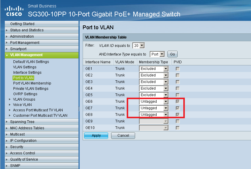
- Log in to the switch and go to VLAN Management -> VLAN Settings, create a VLAN for the Swisscom devices

- Assign the ports to the VLAN
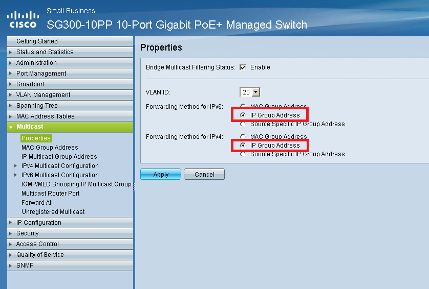
- Under Multicast -> Properties activate and select the VLAN in the drop down. Activate for IPV4 the forwarding method IP Group Address
- In Multicast -> IPv4 Multicast Configuration ->IGMP Snooping activate IGMP Snooping Status and IGMP Querier Status
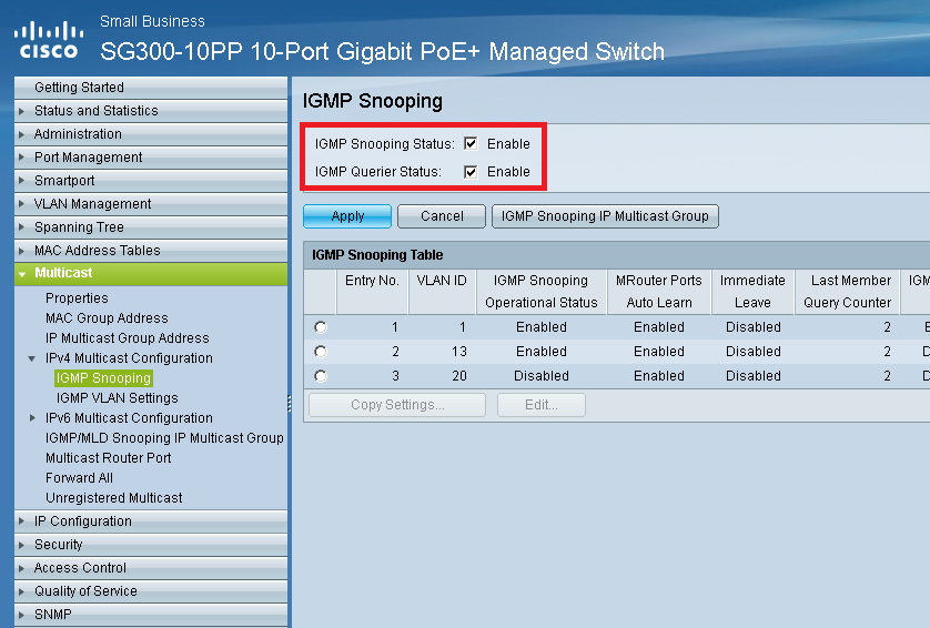
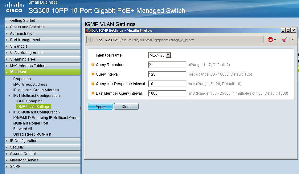
- Select VLAN 20 and hit Edit for additional settings
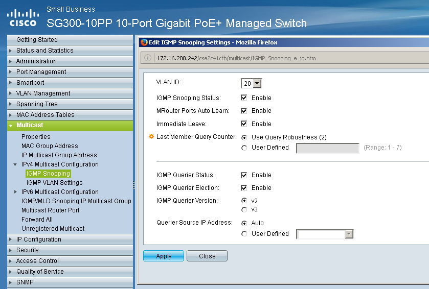
- Multicast -> IPv4 Multicast Configuration -> IGMP VLAN Settings.
Select the VLAN 20 and set accordingly
- If the switch still is flooded an additional setting can be done under Multicast – Unregistered Multicast.
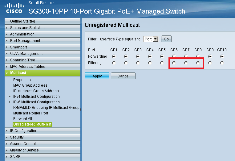 Activate filtering of all unregistered multicast.
Symetrix triggers ADA PTM-1645 and Lexicon DD-8
Have you ever heard a Symetrix Radius or Edge combined with a ADA PTM-1645VC or a Lexicon DD-8?
Even though that combination sounds good, its a breeze to combine them technically. No need to trigger over control systems, doing whatever programming.
ADA PTM-1645
Using this prebuild super-module for Symetrix Composer all PTM’s can be controlled from one serial port of a Symetrix unit. Setup instructions are inside the supermodule
Daisy Chain of PTM’s is supported.
Cabling: Symetrix RX goes to ADA ring, TX to tip, ground to ground
Download here (login needed)
PTM-1645VC Trigger
![CropperCapture[573]](https://technet.genesis-technologies.ch/wp-content/uploads/2014/08/CropperCapture573.png)
Lexicon DD-8
The DD-8 needs to be controlled over a single trigger, using one control output of a Symetrix unit. All 4 zones of the DD-8 are supported, merged.
Setup instructions are inside the supermodule
Download here (login needed)
DD-8 Trigger
![CropperCapture[572]](https://technet.genesis-technologies.ch/wp-content/uploads/2014/08/CropperCapture572.png)
Setup a Cisco SG300 / 500 switch for Dante
Disclaimer: Genesis Technologies cannot test every firmware from Cisco, so the following settings may or may not work. We do not recommend using SG350 and SG550 series switches as firmware quality varies widely. Take the Netgear 4300 series instead, they’re at least made for SDVoE, which has the same requirements as Dante. Again we cannot take over responsibility for products not made by us
- Update the Switch to the latest firmware and boot code
- Before you start make sure you have a TFTP client installed on your PC, if not you can use Solarwinds TFTP Server. Once installed download the latest Firmware from the Cisco website.Open Solarwinds TFTP server go to File -> Configure and set the TFTP Root Server Directory to the folder you have placed the Firmware files.
![CropperCapture[509]](https://technet.genesis-technologies.ch/wp-content/uploads/2014/06/CropperCapture509-294x300.png)
- Start the Service and close this window. The bottom bar of the main window should now confirm that the server runs
![CropperCapture[510]](https://technet.genesis-technologies.ch/wp-content/uploads/2014/06/CropperCapture510-300x148.png)
- Make sure all firewalls are disabled or correct configured.
Log in to your switch and go to Administration -> File management – >Upgrade… and select to upgrade the firmware.![CropperCapture[512]](https://technet.genesis-technologies.ch/wp-content/uploads/2014/06/CropperCapture512-300x182.png)
- Follow the procedure displayed by the firmware upgrade process. Once done upgrade the boot code
![CropperCapture[513]](https://technet.genesis-technologies.ch/wp-content/uploads/2014/06/CropperCapture513-300x182.png)
- Again follow the procedure displayed by the firmware upgrade process.Then select to use the new loaded firmware on the next start
![CropperCapture[514]](https://technet.genesis-technologies.ch/wp-content/uploads/2014/06/CropperCapture514-300x178.png)
- Do a reboot, Administration -> File management – >Reboot.
Let your switch reboot, it takes some minutes. It will look like dead for a while, do not do anything, don’t unplug the mains, it will boot fine.Its important that all switches have the same firmware version, do this procedure on every switch in your network, or at least on the ones that are used for Dante
- Before you start make sure you have a TFTP client installed on your PC, if not you can use Solarwinds TFTP Server. Once installed download the latest Firmware from the Cisco website.Open Solarwinds TFTP server go to File -> Configure and set the TFTP Root Server Directory to the folder you have placed the Firmware files.
- Set the switch to a static IP settings
In Administration ->Management Interface -> IPv4 Interface set the switch to a free static IP
![CropperCapture[518]](https://technet.genesis-technologies.ch/wp-content/uploads/2014/06/CropperCapture518-300x148.png)
- Define DNS settings
Enable the use of DNS in IP Configuration -> Domain Name System -> DNS Settings and add at least 2 known good DNS servers to the list
![CropperCapture[519]](https://technet.genesis-technologies.ch/wp-content/uploads/2014/06/CropperCapture519-300x253.png)
- adjust system time
A very important thing is that the switches are synchronized in time. Not only that the logs are more clear if time is right, the complete network management traffic between the switches is taking advantages of a correct time.- Administration -> Time settings -> System Time enable the Main Clock Source (SNTP Servers) and set also the correct time zone
![CropperCapture[520]](https://technet.genesis-technologies.ch/wp-content/uploads/2014/06/CropperCapture520-300x181.png)
- Enable afterwards the SNTP Client Unicast in Administration -> Time settings -> SNTP Unicast and add at lest two time sources
![CropperCapture[521]](https://technet.genesis-technologies.ch/wp-content/uploads/2014/06/CropperCapture521-300x91.png)
If the config is correct the status is up and the Last Response is accurate
- Administration -> Time settings -> System Time enable the Main Clock Source (SNTP Servers) and set also the correct time zone
- Create a VLAN for Dante
We assume here that you are already logged in in the Switch..- To create a new VLAN go to Vlan Management -> Vlan Setings an add a new one
![CropperCapture[515]](https://technet.genesis-technologies.ch/wp-content/uploads/2014/06/CropperCapture515-300x210.png)
- Next we have to define which port that contains traffic for that virtual lan. But before we have to define the capabilities of each port in therms of VLAN. 3 different port settings can be set in Vlan Management -> Interface Se tings. From Cisco manual:
- General—The interface can support all functions as defined in the IEEE 802.1q specification. The interface can be a tagged or untagged member of one or more VLANs.
- Access—The interface is an untagged member of a single VLAN. A port configured in this mode is known as an access port.
- Trunk—The interface is an untagged member of one VLAN at most, and is a tagged member of zero or more VLANs. A port configured in this mode is known as a trunk port.
- So for us that means that all Dante devices must be connected to a port that is set to access, all ports that are connected to other switches must be Trunk or General
![CropperCapture[516]](https://technet.genesis-technologies.ch/wp-content/uploads/2014/06/CropperCapture516-300x86.png)
- After we have set our port settings right we do assign which VLAN goes over which port.
A trunk usually transports all VLAN’s to the next switch, therefore we can set the uplink port to transport all VLAN’s
![CropperCapture[517]](https://technet.genesis-technologies.ch/wp-content/uploads/2014/06/CropperCapture517-300x98.png)
The picture above show that port 1-5 are uplinks to other switches 6-8 are access ports for simple Dante devices. UP means that this VLAN (usually 1) is the default non tagged Lan which is assigned on the port (If you connect your PC without VLAN config on the network card you end up in this network).
T means that this VLAN is tagged only available on this port. The pages VLAN Management -> Port VLAN Membership and VLAN Management -> Ports to VLAN do show and set the same settings.
- To create a new VLAN go to Vlan Management -> Vlan Setings an add a new one
- Disable Energy Efficient Ethernet EEE
Anyhow the Cisco switches are very good in saving energy and disabling partially the ports Dante can be affected by such events. Therefore this service should be disabled. (Not every switch does support EEE, if not available its not built in)
![CropperCapture[522]](https://technet.genesis-technologies.ch/wp-content/uploads/2014/06/CropperCapture522-300x133.png)
In ports overview it should look like that
![CropperCapture[523]](https://technet.genesis-technologies.ch/wp-content/uploads/2014/06/CropperCapture523-300x57.png)
- Multicast settings
Dante supports IGMP, a communication protocol to manage multicast. Using that protocol the switch can manage multicast’s and decide which port should be included in the multicast, save CPU and port capacity for ports that are not involved.- First we have to enable the Bridge Multicast Filtering Status in Multicast -> Properties for the VLAN we use for Dante. As Forwarding Method select IP Group Address
![CropperCapture[524]](https://technet.genesis-technologies.ch/wp-content/uploads/2014/06/CropperCapture524-300x118.png)
- Each VLAN needs to be enabled with IGMP. In Multicast -> IGMP Snooping select all vlans which contains Dante traffic and enable the IGMP snooping status
![CropperCapture[526]](https://technet.genesis-technologies.ch/wp-content/uploads/2014/06/CropperCapture526-300x106.png)
- Select each IGMP enabled VLAN and press edit. Do the following settings
![CropperCapture[527]](https://technet.genesis-technologies.ch/wp-content/uploads/2014/06/CropperCapture527-300x180.png)
Important: If there are multiple switches in the setup only activate the IGMP Querier on one switch and configure the Multicast Router Port accordingly.
IGMP querier does only work if the switch has a IP address in the same network segment it should query (Querier Source IP Address). Take care if you have VLANS on different network segments, the switch must have a matching IP to send the query’s. Maybe Layer 3 must be activated to achieve this…More info on multi- switch IGMP config: https://confluence.avt.tech/pages/viewpage.action?pageId=51381181. From this step on our switch auto-detects multicast ‘s and forward them to the ports needed. This auto-detect needs to be tuned a little for Dante. - (STEPS d->g ARE USUALLY NOT NEEDED AS THE SWITCH LOOKUP THE CORRECT SETTINGS BY ITSELF: SO DO NOT PERFORM THESE STEPS!)The table in Multicast ->IP Multicast Group Address shows the already detected multicast IP addresses, as well custom addresses can be inserted. So we make sure the two addresses 224.0.1.129 (PTP) and 224.0.0.251 (MDNS) are in this list and assigned to the ports needed (Ports that are included in the Dante VLAN) as static
![CropperCapture[528]](https://technet.genesis-technologies.ch/wp-content/uploads/2014/06/CropperCapture528-300x238.png)
- Looking at Multicast -> Multicast Router
![CropperCapture[531]](https://technet.genesis-technologies.ch/wp-content/uploads/2014/06/CropperCapture531-300x121.png)
The different settings static, Forbidden, None are explained in the help of the switch. Dynamic means that the switch has detected the port already, so change this to static. Once changed, the switch knows already the correct settings, so after a power loss the right settings are immediately applied, the auto detect delay is gone. - For uplink connections from switch to switch also activate in Multicast -> Multicast Router Port the port to static forward all traffic.
The picture above shows that port 10 is an uplink, port 1 is not disturbed in any case with Dante multicast’s. For devices which are maybe in the same VLAN but are not Dante devices the setting forbidden should be chosen. The two multicast addresses we added are now registered multicast’s, means the switch knows exactly what to do with the traffic. - For Dante audio multicast’s and other devices multicast’s we need to make sure that the unregistered multicast’s are forwarded and auto-detected. Multicast -> Unregistered Multicast let us define exactly this settings. Port 1 does not need any multicast, therefore we define Filtering for this port. All other are in Forwarding mode.
![CropperCapture[532]](https://technet.genesis-technologies.ch/wp-content/uploads/2014/06/CropperCapture532-300x121.png)
- First we have to enable the Bridge Multicast Filtering Status in Multicast -> Properties for the VLAN we use for Dante. As Forwarding Method select IP Group Address
- Setup QoS to prioritize PTP (Dante clock messages)
- Quality of Service -> General -> QoS Properties set the QoS mode to Advanced
![CropperCapture[533]](https://technet.genesis-technologies.ch/wp-content/uploads/2014/06/CropperCapture533-300x157.png)
- Then we have to correct the queue settings
![CropperCapture[534]](https://technet.genesis-technologies.ch/wp-content/uploads/2014/06/CropperCapture534-300x137.png)
- Quality of Service -> QoS Advanced Mode-> Global Settings we need finally to set the Trust mode to DSCP and the Default Mode Status to Trusted
![CropperCapture[535]](https://technet.genesis-technologies.ch/wp-content/uploads/2014/06/CropperCapture535-300x168.png)
- Quality of Service -> General -> QoS Properties set the QoS mode to Advanced
![CropperCapture[509]](https://technet.genesis-technologies.ch/wp-content/uploads/2014/06/CropperCapture509.png)
![CropperCapture[510]](https://technet.genesis-technologies.ch/wp-content/uploads/2014/06/CropperCapture510.png)
![CropperCapture[512]](https://technet.genesis-technologies.ch/wp-content/uploads/2014/06/CropperCapture512.png)
![CropperCapture[513]](https://technet.genesis-technologies.ch/wp-content/uploads/2014/06/CropperCapture513.png)
![CropperCapture[514]](https://technet.genesis-technologies.ch/wp-content/uploads/2014/06/CropperCapture514.png)
![CropperCapture[518]](https://technet.genesis-technologies.ch/wp-content/uploads/2014/06/CropperCapture518.png)
![CropperCapture[519]](https://technet.genesis-technologies.ch/wp-content/uploads/2014/06/CropperCapture519.png)
![CropperCapture[520]](https://technet.genesis-technologies.ch/wp-content/uploads/2014/06/CropperCapture520.png)
![CropperCapture[521]](https://technet.genesis-technologies.ch/wp-content/uploads/2014/06/CropperCapture521.png)
![CropperCapture[515]](https://technet.genesis-technologies.ch/wp-content/uploads/2014/06/CropperCapture515.png)
![CropperCapture[516]](https://technet.genesis-technologies.ch/wp-content/uploads/2014/06/CropperCapture516.png)
![CropperCapture[517]](https://technet.genesis-technologies.ch/wp-content/uploads/2014/06/CropperCapture517.png)
![CropperCapture[522]](https://technet.genesis-technologies.ch/wp-content/uploads/2014/06/CropperCapture522.png)
![CropperCapture[523]](https://technet.genesis-technologies.ch/wp-content/uploads/2014/06/CropperCapture523.png)
![CropperCapture[524]](https://technet.genesis-technologies.ch/wp-content/uploads/2014/06/CropperCapture524.png)
![CropperCapture[526]](https://technet.genesis-technologies.ch/wp-content/uploads/2014/06/CropperCapture526.png)
![CropperCapture[527]](https://technet.genesis-technologies.ch/wp-content/uploads/2014/06/CropperCapture527.png)
![CropperCapture[528]](https://technet.genesis-technologies.ch/wp-content/uploads/2014/06/CropperCapture528.png)
![CropperCapture[531]](https://technet.genesis-technologies.ch/wp-content/uploads/2014/06/CropperCapture531.png)
![CropperCapture[532]](https://technet.genesis-technologies.ch/wp-content/uploads/2014/06/CropperCapture532.png)
![CropperCapture[533]](https://technet.genesis-technologies.ch/wp-content/uploads/2014/06/CropperCapture533.png)
![CropperCapture[534]](https://technet.genesis-technologies.ch/wp-content/uploads/2014/06/CropperCapture534.png)
![CropperCapture[535]](https://technet.genesis-technologies.ch/wp-content/uploads/2014/06/CropperCapture535.png)
References:
Yamaha Proaudio setup pages for Dante http://www.yamahaproaudio.com/global/en/training_support/selftraining/dante_guide/index.jsp
Symetrix knowledge-base http://www.symetrix.co/support/knowledge-base/
Technet article Dante networking: Ports and protocols
Audinate website FAQ: https://www.audinate.com/index.php?option=com_content&view=article&id=187
Allen&Heath Understanding Dante http://www.allen-heath.com/media/Understanding+M-DANTE+-+rev+18dec12.pdf
Wikipedia IGMP article http://en.wikipedia.org/wiki/Internet_Group_Management_Protocol
Wikipedia Qos article http://en.wikipedia.org/wiki/Quality_of_service
Cisco integrated help in the switch interface (top right corner)
AVT Tech: https://confluence.avt.tech/pages/viewpage.action?pageId=51381181 or direct link to a PDF of the site TKB-51381181-301018-1616-70
Dante networking: Ports and protocols
A few facts and figures about Dante packets on the Network
Protocol and ports used by Dante, all UDP
| Protocol | Src. IP | Src. Port | Dest. IP | Dest. Port | Description |
|---|---|---|---|---|---|
| PTP (v1) | All Dante devices | all | 224.0.1.129 | 319, 320 | Clock, Synchronization of Dante network |
| MDNS | All Dante devices | all | 224.0.0.251 | 5353 | Device info for Dante Controller Software |
| unknown multicast | All Dante devices | all | 224.0.0.231 | 8700-8704, 8800 | Dante Control and Monitoring |
| unknown unicast | All Dante devices | all | Unit Receiving stream | 4440,4444, 4455 | Dante Routing |
| unknown multicast | All Dante devices | all | 239.255.x.x | 4321 | Audio Broadcast |
| unknown unicast | All Dante devices | all | Unit Receiving stream | 14336-14600 | Audio Unicast |
Multi and unicasts
- Be aware that multicast’s are always sent, even when there is no “subscriber”. So the network components can be overloaded even if nowhere sound play’s
- Unicast’s are only sent if there is a valid routing and the receiving Dante unit is alive. Maximum 2 concurrent Dante Unicast can be sent per unit/stream. A third assigned unit will play nothing until one of the two unicast’s are free
How to find a Kaleidescape server with unknown IP address
There are 3 ways.:
First and easiest: Using local link (Kaleidescape KB article [K000037])
In the rare case that the Kaleidescape server has an unknown static IP address and the server is on a different subnet than the computer, it is possible to access the browser interface using an alternate address, known as the link local address.
Follow the procedure below to access the browser interface of the Kaleidescape server using the link local address. You should understand networking in the Windows operating system to safely make the changes. Before you attempt this procedure, try the other methods described in www.kaleidescape.com/go/browser-interface.
- Use a computer with a Windows operating system. (The following steps are for Windows XP.)
- Connect the computer by an Ethernet patch cable to the same switch as the Kaleidescape server. A wireless connection will not work.
- Disable any firewall.
- Check that NetBIOS name resolution is enabled. If not, install Bonjour Print Services for Windows according to the instructions at http://support.apple.com/kb/DL999.
- On the computer, select Start > Settings > Network Connections > LAN. The LAN Status window appears.
- Click Properties. The LAN Properties window appears.
- In the LAN Properties window, scroll down the list of items and select Internet Protocol (TCP/IP). Click Properties. The Internet Protocol (TCP/IP) Properties window appears.
- Take note of the settings in the Internet Protocol (TCP/IP) Properties window. You will change these settings, and then undo the changes.
- Click Use the following IP address and type 169.254.101.101 for IP address and 255.255.0.0 for Subnet mask. Do not change any other fields.
- Click OK. The Internet Protocol (TCP/IP) Properties window closes.
- Click Close in the LAN Properties window.
- Click Close in the LAN Status window, if still open.
- Check that the Kaleidescape server is powered on and connected to the network switch; the server front panel should glow blue.
- Find the serial number of the server.
- The link local address of the server is ll- followed by the 12-character serial number of the server. Here “ll” is two instances of the letter l. For example, if the server serial number is 0000 0001A2B3, then the link local address is ll-00000001A2B3. Enter http://ll-00000001A2B3 in a web browser. The browser interface should appear.
- In the browser interface, select the SETTINGS tab, then select Components in the second row of tab. Click the Settings button for the server. The Network Settings window appears. Configure the network.
- After the Kaleidescape System has been configured, undo the link local address. The link local address is not suitable for normal operation. To undo the link local address, select Start > Settings > Network Connections > LAN on the computer. In the LAN Status window, click Properties. In the LAN Properties window, select Internet Protocol (TCP/IP) and click Properties. Reset the settings in the Internet Protocol (TCP/IP) Properties window to the original settings previously noted. Click OK, then click Close in the LAN Properties window.
The procedure for Mac users is similar, but append “.local” to link local address, for example, http://ll-00000001A2B3.local.
Second way: Take a serial capture (Kaleidescape KB article [K000074])
Don’t do this if a hard disk is amber! Requires a restart which may is dangerous if a disc already is amber/failed. First replace the disc and let rebuild the filesystem
See this PDF: Kaleidescape-Quick-Reference-Retrieving-Diagnostic-Information
The output contains all network information
Third: Connect via serial and set back to DHCP (Kaleidescape KB article [K000027])
If the IP address of a Kaleidescape component cannot be determined, you can reset the IP address by connecting the RS-232 port of the component to a standard DB-9 serial port of a computer with a DB-9 serial cable. Use a straight-through cable for players and a crossover cable for servers. Then configure a serial-capable terminal emulator (e.g. HyperTerm or PuTTY) to 8 data bits, no parity, 1 stop bit (8N1), and no flow control. For a player or disc vault, set it to 19,200 bps and, for a server, set it to 115,200 bps.
Now execute the following commands (followed by [ENTER]) in the terminal emulator to view or set the network settings: (Always copy and past the complete string!)
To get the device’s current network settings: 01/1/GET_NETWORK_SETTINGS:
To set a device to DHCP: 01/1/SET_NETWORK_SETTINGS:0::::::
To set a device to a static address, in this case IP address 192.168.1.222, Subnet Mask of 255.255.255.0, Gateway of 192.168.1.1 and primary and secondary DNS of 4.2.2.2 and 192.168.1.2 respectively: 01/1/SET_NETWORK_SETTINGS:1:192.168.1.222:255.255.255.0:192.168.1.1:4.2.2.2:192.168.1.2:
Once you have changed a component’s IP address, reboot it for the changes to take effect.